Learn how to assemble and rig F34 aluminum box truss safely with step-by-step setup instructions, load checks, and essential stage rigging best practices.
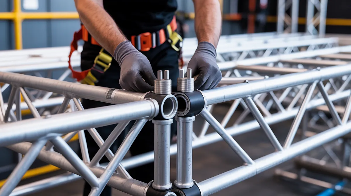
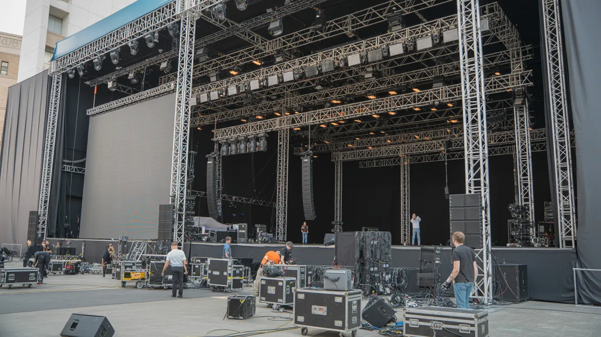
F34 aluminum box truss is a staple in professional stage equipment, concert production, trade show builds, and event rigging because it offers an excellent balance of strength, modularity, and manageable weight. Whether you are building a ground-supported goal post, a lighting grid, or a compact entry arch, safe truss assembly depends on proper planning, correct hardware, and disciplined rigging practices. This guide walks through how to assemble and rig F34 truss step by step, with a focus on stability, alignment, and jobsite safety.
Before You Start: Planning and Inspection
Before any section of F34 truss is lifted, verify the layout, span lengths, intended loads, and support points. F34 square truss typically measures 290mm x 290mm, so every connection must be made with compatible components and properly rated hardware. Never assume a structure is safe simply because it looks symmetrical; load paths, center of gravity, and base footprint all matter.
Inspect every component before assembly:
- Truss sections for bends, cracks, gouges, or deformed sleeves
- Spigots, pins, and clips for wear, missing hardware, or corrosion
- Base plates for flatness and intact welds
- Corner blocks for alignment damage and fit
- Top plates and accessories for secure attachment points
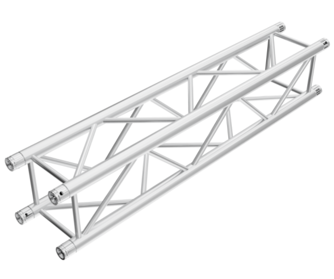
For straight spans, the F34 Truss - 1m - 290mm x 290mm and 2m - F34 Truss - 290mm x 290mm are common building blocks. Use the 1m length for tighter fits, compact scenic frames, or short cross members, and the 2m section when you need fewer connections and a cleaner load path across a larger span.
Step 1: Set Up a Level Work Area
Build on a clean, level surface whenever possible. Uneven ground introduces torsion and can cause a truss tower or frame to rack during assembly. If the site is not level, use shimming or leveling methods approved for the venue and never rely on loose objects as makeshift support.
Lay out all truss sections in the order they will be connected. This reduces handling errors and helps the crew verify the design before lifting anything overhead.
Step 2: Position the Base Plates
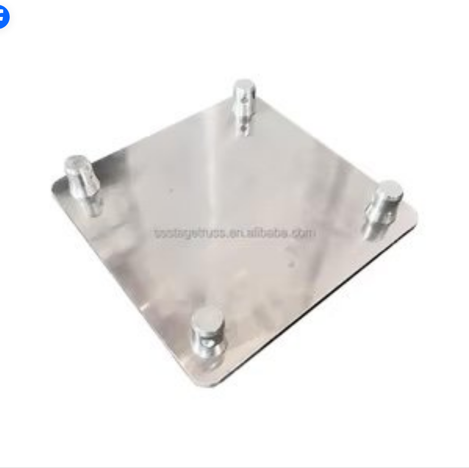
A stable truss structure starts at the floor. Use a correctly sized base plate to spread the load and improve resistance to tipping. The F34 Base Plate - 600mm x 600mm x 10mm is suitable for smaller or lighter ground-supported structures, while the F34 Base Plate - 800mm x 800mm x 10mm provides a larger footprint for greater stability in taller or more heavily loaded builds.
When selecting a base plate, consider:
- The overall height of the truss structure
- The expected live load from lighting, audio, scenic, or décor elements
- Whether the structure will be free-standing or tied into additional support
- Venue conditions such as audience proximity, wind exposure, and traffic flow
Place the base plates exactly where the truss uprights will land. Confirm orientation before attaching vertical members, especially if anchor points, cable runs, or braces must face a specific direction.
Step 3: Assemble the Ground Section
Connect the first truss section to the base plate using the manufacturer-approved interface and hardware. If your design includes a corner, install the appropriate connector now rather than trying to force alignment later. The 2-Way Corner, F34, 290mm x 290mm is ideal for creating a strong 90-degree turn, such as a rectangular goal post, perimeter frame, or lighting wing.
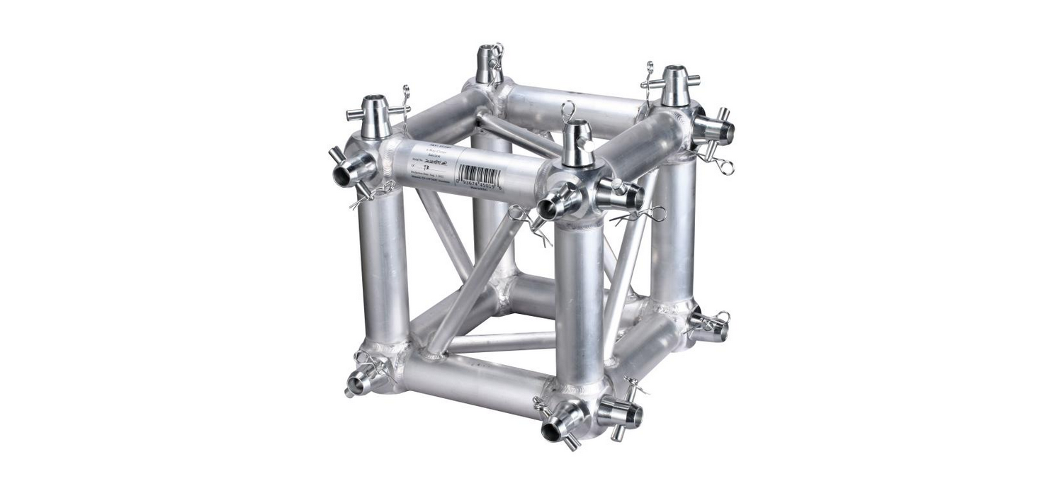
For more complex layouts, the 6-Way Corner, F34, 290mm x 290mm can join multiple truss directions in a single node. This is useful for central hubs, multi-branch lighting grids, or structures where several spans meet at one point. Because multi-way junctions can concentrate forces, confirm that the configuration is supported by the full structural plan and load calculation.
At this stage, keep all connections loose enough for minor alignment adjustments. Once the geometry is confirmed, tighten and secure the joints according to the system’s rigging method.
Step 4: Build Verticals and Horizontal Spans
Once the base is stable, add vertical sections one at a time. Lift with proper crew coordination and maintain control of the member at all times. A common mistake is to build too much of the structure before checking plumb and square; instead, verify alignment after each major connection.
Recommended sequence for a simple rectangular structure:
- Attach both vertical uprights to the base plates.
- Connect the top span using 1m or 2m F34 truss sections as required.
- Add the opposite corner or end section to close the frame.
- Check plumb, level, and diagonal measurements before final tightening.
Measure diagonally from corner to corner to confirm the frame is square. Equal diagonal measurements indicate that the structure is not twisted and that loads will be distributed more evenly.
Step 5: Install the Top Plate or Load Interface
For overhead lighting, hoists, or distributed scenic load points, the top connection must be secure and correctly centered. The Aluminium Top Plate - F34 - 300mm x 300mm provides a stable connection point on top of F34 box truss and is commonly used where equipment must be mounted cleanly at the crown of a vertical tower or frame.
Make sure the top plate is:
- Fully seated on the truss
- Aligned with the intended load direction
- Secured using the correct fasteners or coupling method
- Compatible with the planned attachment hardware
If the top plate will support suspended equipment, ensure all secondary rigging devices, such as safety bonds or independent backup points, are installed according to applicable venue and manufacturer requirements.
Step 6: Rig Loads Safely
When hanging lights, speakers, banners, or scenic pieces, respect the rated capacity of every component in the chain. The safe working load is determined by the weakest link, which may be the truss section, corner, plate, clamps, hoist, or attachment point. Never exceed the lowest rated part of the system.
Use these best practices:
- Center loads whenever possible to minimize bending moments
- Distribute multiple fixtures evenly across the span
- Use compatible clamps and rated rigging hardware
- Attach secondary safety cables to overhead devices where required
- Keep cables neat to avoid accidental pull-down forces
For longer spans, the 2m F34 truss can reduce the number of junctions, which often improves structural continuity. However, longer spans also require more attention to deflection and load placement. If the structure includes directional changes or multiple branch points, the 6-way corner can simplify the build, but only if it is incorporated into the design with proper support.
Step 7: Final Safety Checks Before Use
Before the structure is placed into service, conduct a full final inspection. This step is essential for stage truss safety and should never be skipped, even for recurring builds.
- Verify all pins, clips, and locking devices are installed
- Confirm all joints are fully seated
- Check that the base plates are flat and stable
- Inspect the entire structure for plumb and level
- Verify that no load exceeds the planned capacity
- Test the structure for unwanted movement before adding final overhead load
If the structure is tall, complex, or installed in a public-facing environment, have a qualified rigging professional review the build. Extra verification is especially important for exhibition halls, touring installs, and venue changes where conditions vary from show to show.
Common Mistakes to Avoid
Even experienced crews can make assembly errors when time is tight. Avoid these frequent issues:
- Using mismatched components: Always confirm the truss system and connector compatibility.
- Skipping the base footprint check: A narrow or unstable footprint increases tipping risk.
- Overloading one side: Uneven loading can twist a frame or tower.
- Ignoring diagonal measurements: Small geometry errors become major stability problems at height.
- Rushing the final inspection: Loose hardware can fail under vibration or movement.
Best Practices for Long-Term Safety
To extend the life of your aluminum box truss and maintain safe performance, store components in a dry environment and clean them after use. Keep pins organized, replace damaged parts immediately, and retire any section that shows structural deformation. A well-maintained F34 system is not only safer but also faster to assemble because pieces fit correctly and align predictably.
It is also smart to create a standard build checklist for recurring productions. Include truss lengths, corner types, base plate sizes, attachment points, and final inspection steps. Standardization reduces human error and helps crews repeat safe setups under pressure.
Conclusion
Safely assembling and rigging F34 aluminum box truss comes down to preparation, correct component selection, and disciplined installation practices. Start with stable base plates, build square and level, use the right corner pieces for the layout, and verify every connection before any overhead load is introduced. Whether you are using 1m or 2m F34 truss, a 2-way corner, a 6-way corner, or a 300mm x 300mm top plate, each part plays a specific role in the overall safety and performance of the structure. By following these step-by-step instructions and treating every setup as a safety-critical build, you can create reliable stage structures that perform well in professional event environments.
Stay Updated
Get notified about new products, deals, and industry guides.
No spam. Unsubscribe anytime.
Products Mentioned in This Guide
Shop the equipment referenced in this article.
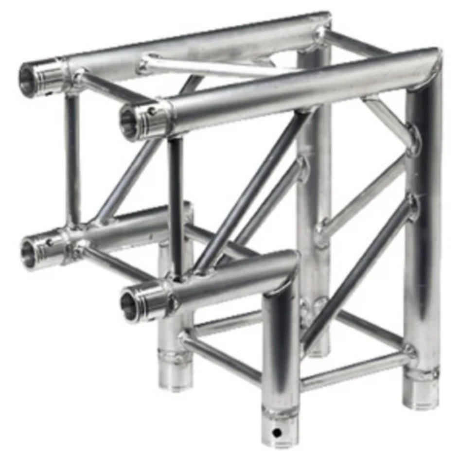
F34 2-Way 90° Corner Block | 290mm Square Box Truss Junction | 6061-T6 Aluminum
$189.99

F34 Base Plate 600mm × 600mm × 10mm | Ground Support Plate for 290mm Box Truss
$199.99
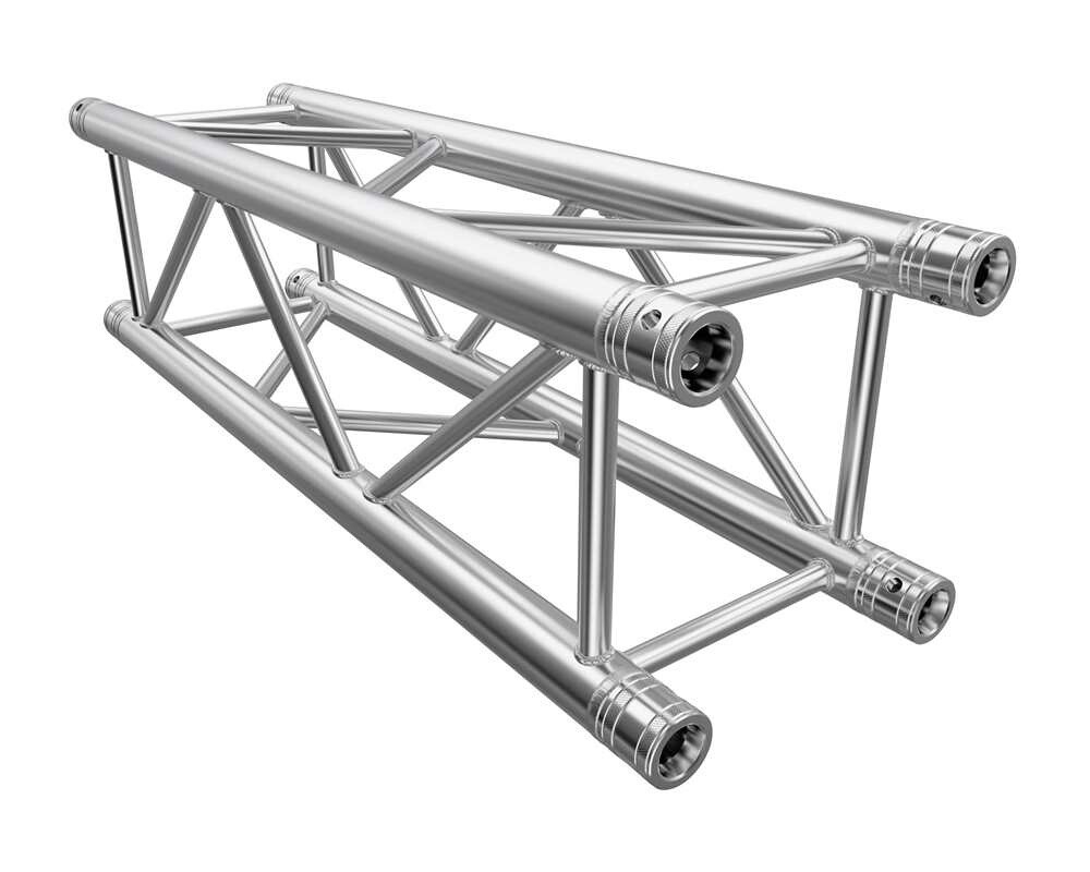
F34 1m (3.28ft) Straight Square Aluminum Truss | 290mm Box Truss | CCS Conical Connection
$179.99$155.00
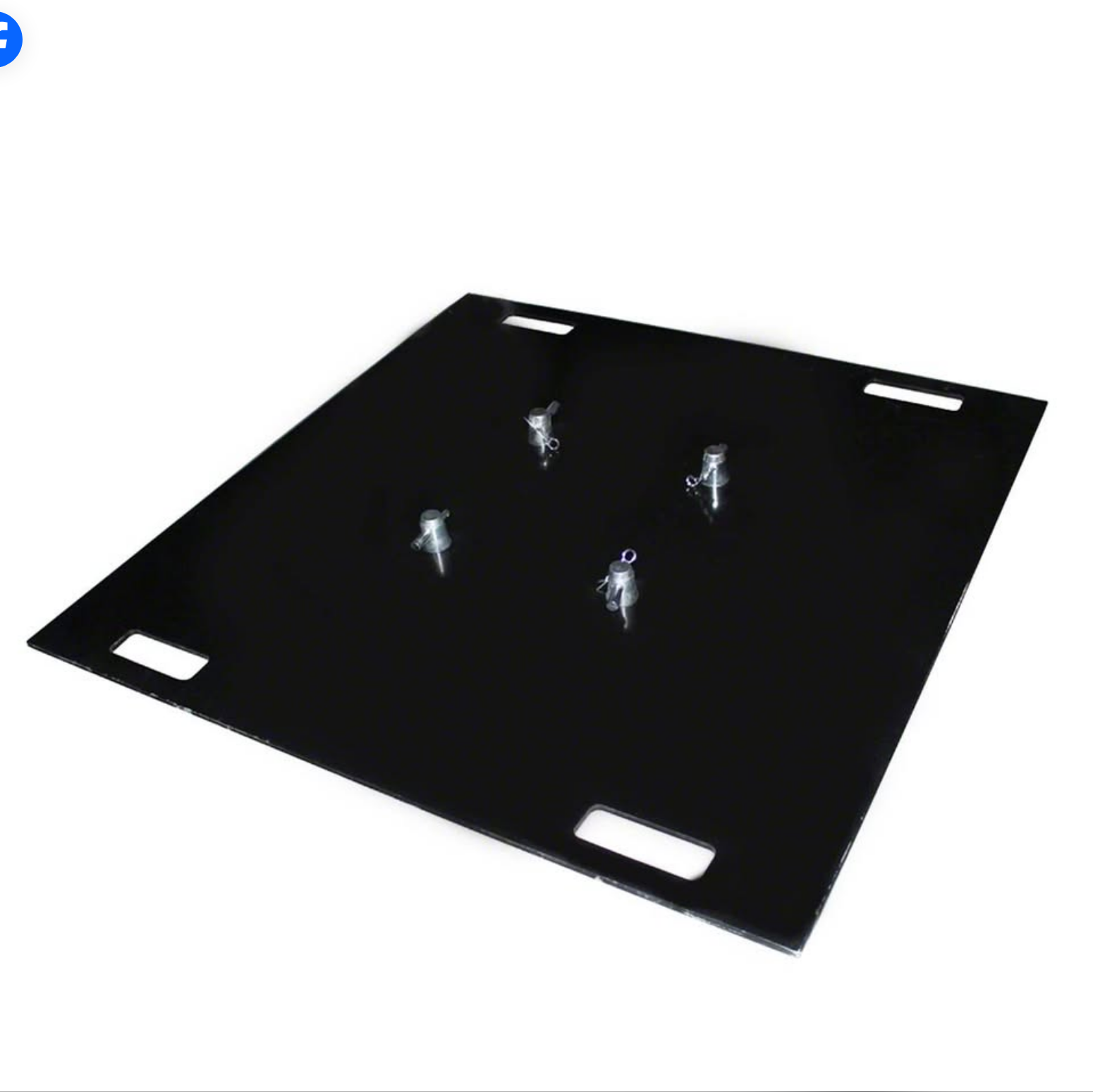
F34 Base Plate 800mm × 800mm × 10mm | Heavy Duty Ground Support for 290mm Box Truss
$274.99
F34 Aluminum Top Plate 300mm × 300mm | Truss Top Cap for 290mm Box Truss
$139.99
F34 2m (6.56ft) Straight Square Aluminum Truss | 290mm Box Truss | CCS Conical Connection
$349.99$300.00
F34 6-Way Corner Junction Block | 290mm Square Box Truss Connector | 6061-T6 Aluminum
$274.99
Related Guides
Truss Load Capacity and Structural Safety: Understanding Weight Ratings, Span Limits, and Engineering Calculations for Stage Rigging
A practical guide to truss load capacity, span limits, and structural safety for stage rigging. Learn how to evaluate weight ratings, understand real-world load conditions, and choose the right F34 truss components for safe, professional event builds.
Planning Your First Event Stage Setup: A Beginner’s Checklist for Truss, Lighting, and Rigging Equipment
A simple, safety-focused checklist for choosing truss, lighting clamps, base plates, and rigging gear for your first stage setup.
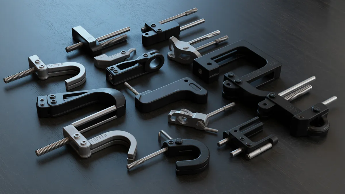
Stage Lighting Clamps Explained: C-Clamps vs Coupler Clamps vs Trigger Clamps
Compare C-clamps, coupler clamps, and trigger clamps to choose the safest, fastest stage lighting clamp for your truss or pipe.